English
 عربى
عربى हिंदी
हिंदीHigh Pressure Equipment 101: Valves, Fittings & Tubing for 30k-150k psi
Jun 05, 2026
Content
What is High Pressure Equipment?
Any system component rated for continuous operation at or above 10,000 psi falls squarely into the high pressure equipment category. In practice, offshore wellheads, hydrogen fueling stations, and supercritical fluid research routinely push that boundary to 60,000 psi and beyond. A single mis‑specified fitting here does not leak—it liberates stored energy fast enough to fracture steel. That is why engineers treat pressure rating not as a marketing number but as a hard design constraint.
The same manufacturer that produces a laboratory 30,000 psi needle valve may also supply a 150,000 psi autoclave connection. The core disciplines remain constant: material selection, thread geometry, and verification testing. What changes is the consequence envelope. A 30k psi test bench in a university lab demands repeatable sealing; a 60k psi frac manifold demands survival through abrasive slurry and cyclic fatigue. The table below maps common pressure classes to the industries that depend on them.
| Pressure Class (psi) | Typical Applications | Component Example |
|---|---|---|
| 30,000 | Laboratory research, chemical injection, small‑scale hydrostatic testing | 30k needle valve, coned‑and‑threaded tee |
| 40,000 | Pilot‑scale supercritical extraction, mid‑range waterjet cutting | 40k check valve, rupture disc assembly |
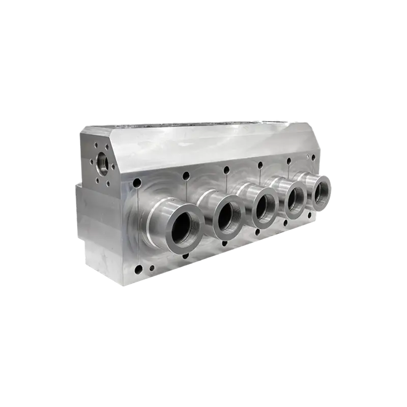
| 60,000 | Oil and gas fracturing, deepwater BOP control, large‑diameter autoclaves | Fluid end block, 60k safety head |
| 100,000 | High‑pressure physics, diamond anvil backup, ultra‑deep well intervention | 100k tubing nipple, anti‑vibration gland |
| 150,000 | Extreme‑pressure material synthesis, specialized isostatic pressing | 150k tee, instrument valve |
A 30k‑psi fitting and a 60k‑psi fitting may look alike. Internally, the wall thickness, grain direction, and heat‑treatment protocol are fundamentally different. That difference is what this article unpacks.
Key Components of High Pressure Systems
A high pressure circuit is only as strong as its least‑controlled interface. Six component families do most of the heavy lifting: valves, fittings, tubing, seals, rupture devices, and vibration‑damping assemblies. Each one matters.
Valves
Needle valves provide fine flow regulation and tight shutoff at pressures up to 150,000 psi. Their stainless or alloy steel stems feature a hard‑seated, non‑rotating tip to prevent galling. Check valves prevent backflow that could slam a pump or collapse a filter housing; at 60k psi, a sticking poppet can mean a six‑figure rebuild. Safety heads and rupture discs serve as the final pressure relief—set at a calibrated burst pressure, they protect both operators and downstream instrumentation. When specifying any of them, demand a certified flow coefficient (Cv) and a documented opening pressure tolerance.
Fittings and Tubing
High pressure fittings use a compact coned‑and‑threaded design that eliminates the large hex bodies of traditional NPT connections. This geometry accommodates larger bore diameters for higher flow rates without sacrificing strength. Coned connections are available as tees, crosses, elbows, and unions. Tubing is typically cold‑drawn 316 stainless steel or nickel alloys, supplied in 1/4 in, 3/8 in, and 9/16 in outside diameters with wall thickness computed per ASME B31.3.
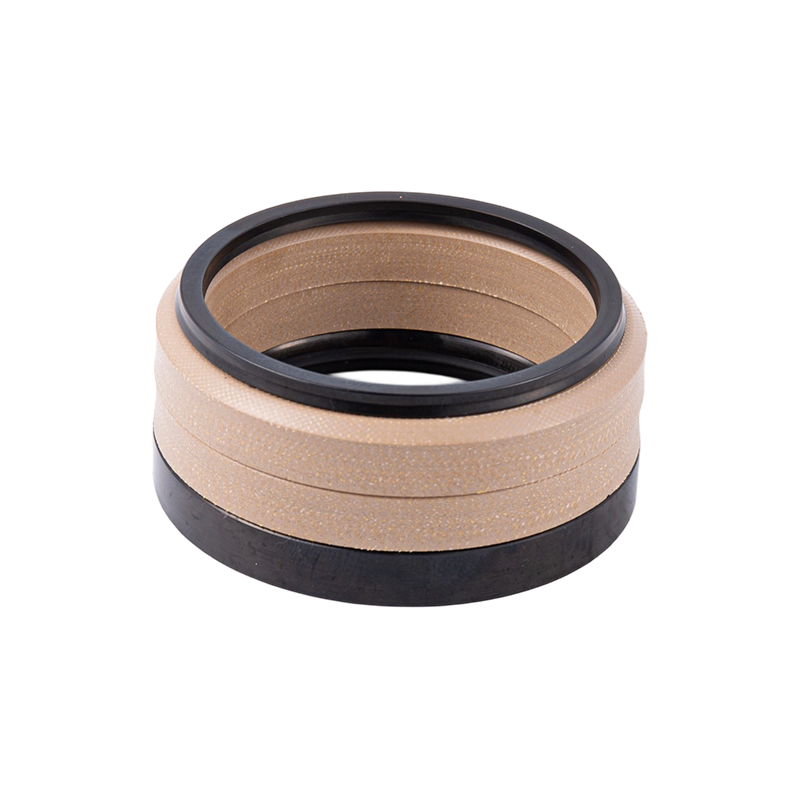
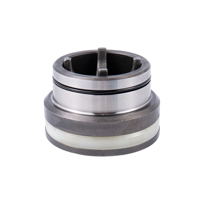
Seals and Anti‑Vibration Assemblies
Plunger packing and gland seals are the frontline defense against process fluid escape. In fracturing environments, a worn packing seal can cut fluid end life by 40 percent. Anti‑vibration gland assemblies absorb pump‑induced oscillation, keeping the tubing string from work‑hardening at the connection point. When vibration exceeds 10 Hz, displacement is already stressing the root of the thread; that is the threshold for immediate inspection.
Pressure Ratings & Material Selection
Choosing a material for 30,000 psi is different from choosing one for 60,000 psi. At 60k psi, the hoop stress in a 9/16‑in OD tube approaches 180,000 psi—well beyond the yield strength of annealed 316. Engineers must look to cold‑worked or precipitation‑hardened grades. The matrix below cross‑references commonly available materials with their safe operating windows.
| Material | 30k psi Suitability | 60k psi Suitability | Max Temp (°F) | H₂S Service (NACE MR0175) |
|---|---|---|---|---|
| AISI 316 Stainless (annealed) | Yes | No (yield limited) | 1,000 | Yes (up to 60k psi, specific hardness) |
| AISI 316 Cold‑Worked | Yes | Yes | 800 | Yes, with hardness control |
| Alloy 625 (Inconel) | Yes | Yes | 1,200 | Yes, preferred for sour gas |
| 17-4 PH H900 | Yes | Yes | 600 | Not recommended for H₂S |
| Titanium Grade 5 | Yes | Yes | 800 | Yes, excellent corrosion resistance |
The real differentiator is fatigue life, not tensile strength. A 60k psi valve body that survives a 5,000‑psi hydrotest can still crack after 200 hours of 0–60k cyclic service if tiny stress raisers from machining go unremoved. For sour environments containing hydrogen sulfide, adherence to NACE MR0175 is non‑negotiable. That standard dictates maximum hardness (typically HRC 22 for carbon and low‑alloy steels), eliminating options like fully hardened 17-4 PH. Buyers should require material test reports that show actual yield strength and Charpy impact values, not just generic mill certs. For tubing, wall thickness shall be calculated using the ASME B31.3 formula t = P×D / (2S×E + 0.8P), where S is the allowable stress at temperature and E is the longitudinal joint factor. At 60k psi and a 9/16‑in OD, the minimum wall for cold‑worked 316 is 0.083 inches; a supplier offering thinner stock is cutting corners.
Connection Types: Coned‑and‑Threaded vs. Bite‑Type vs. Flanged
The joint is where most high pressure systems fail. Three connection philosophies dominate—and the best one depends entirely on access, vibration, and allowable leak rate.
- Coned‑and‑threaded (C&T). A 58° cone mates with a matching gland, and the threaded sleeve pulls the tubing into the cone. No ferrule bites the tube wall; instead, the tube face itself becomes the sealing surface. This design handles 150,000 psi, offers zero‑clearance assembly, and achieves API 598 Class A (zero leakage) when properly torqued. Assembly time averages four minutes per joint for an experienced technician.
- Bite‑type (ferrule). A metal ferrule cuts into the tubing when the nut is tightened. It is fast to assemble but unreliable above 15,000 psi—the ferrule can slip, and vibration loosens the bite. Leak rates under cyclic loading often fall to ISO 5208 Class C.
- Flanged connections. Gasketed bolt flanges work for large‑bore piping but are impractical at 60k psi; the bolt load required to seat a metal ring gasket becomes enormous, and the flange weight alone can sag small‑bore instrumentation lines.
The decision matrix below makes the trade‑offs explicit.
| Connection Type | Max Pressure (psi) | Seal Reliability (API 598 Class) | Install Time (min/joint) | Vibration Tolerance |
|---|---|---|---|---|
| Coned‑and‑threaded | 150,000 | A (zero leakage) | 4 | High (with gland) |
| Bite‑type | 15,000 | B–C | 2 | Low |
| Flanged (RJ gasket) | 20,000 | A–B | 15 | Medium |
Coned‑and‑threaded is the only choice that scales from lab bench to frac pad without a fundamental design change. For a 60k psi hydrogen compressor discharge line, the margin of safety with C&T is 2.5 times higher than with a ferrule joint. Maintenance crews also prefer it: a single‑and‑a‑quarter turn re‑torque often restores a weeping joint without replacing the tube.
Safety & Maintenance Best Practices
No high pressure equipment is install‑and‑forget. A checklist discipline catches the slow‑developing failures—crevice corrosion under a gland, a slipped thread, a hardened packing—before they become reportable incidents.
Start with torque verification. Every coned connection has a factory‑recommended torque value; at 60k psi, a 9/16‑in sleeve is typically tightened to 25 ft‑lb. Re‑check torque within the first 50 pressure cycles, then every 500 cycles thereafter. Seal inspection follows the operating hours: PTFE‑backed seals in continuous liquid service should be pulled and measured for creep at 500‑hour intervals. Metal‑to‑metal seat seals in valves may run 2,000 hours but require a leak test at half that interval.
Vibration monitoring deserves its own protocol. Install a tri‑axial accelerometer on any piping span longer than 24 inches. When the peak‑to‑peak displacement exceeds 5 mils—or the frequency jumps by more than 10 Hz from baseline—shut down and examine the nearest anti‑vibration gland assembly. A support clamp every 2 meters cuts span resonance dramatically.
The checklist below summarizes daily, weekly, and monthly actions.
- Daily: Visual check for fluid mist around packing nuts; record discharge pressure fluctuation.
- Weekly: Torque‑stripe all critical connections; log vibration spectra.
- Monthly: Hydrostatic proof test on a 10 percent sample of safety heads; measure tube wall thickness at bend apexes with ultrasonic gauge.
- Per shift (fracturing pumps): Inspect plunger clamp bolts and verify lube oil level in the power end—low lube oil accelerates fluid end wear.
How to Choose the Right High Pressure Equipment Supplier
A spec sheet gets you to the short list. What separates a transactional vendor from a long‑term partner is how they respond when the pressure rating alone is not the problem—when you need a modified bore, a Hastelloy stem for CO₂ service, or a replacement part for a 20‑year‑old triplex pump that intersects with no current catalog. Evaluate suppliers across five dimensions.
| Evaluation Criterion | What to Look For | Weight |
|---|---|---|
| Pressure Range & Certification | Documented 60k–150k psi offerings; API 6A, API 598, or ISO 5208 test reports | High |
| Material Traceability | Full mill certs with heat numbers, Charpy values, and NACE MR0175 compliance statements | High |
| Lead Time & Inventory | Standard components in ≤4 weeks; expedited build‑to‑order ≤2 weeks; local stock of seals and plungers | Medium |
| Custom Engineering Capacity | In‑house FEA and machining for non‑standard bore sizes or hybrid materials | Medium |
| Warranty & Aftermarket Support | Minimum 1‑year defect warranty, option to extend to 3 years; access to interchangeable parts for legacy pumps | High |
In oil and gas fracturing, for example, a supplier that can ship a fully forged, stainless‑steel fluid end with replaceable packing bores in three weeks turns an unscheduled outage from a five‑day event into a one‑day swap. That capability does not appear on a price sheet, but it shows up on the downtime ledger. The same principle applies whether you are buying a single 30k psi needle valve for a university reactor or outfitting a six‑pump spread. Ask for a heat‑lot‑specific tensile report for the exact batch of material that will form your components. If the supplier cannot produce it, the savings on unit price become an insurance policy you are writing against your own equipment.