 English
 عربى
عربى हिंदी
हिंदीReciprocating Positive Displacement Pumps: Working Principles, Types & High-Pressure Design
Jun 29, 2026
Content
- 1 What Is a Reciprocating Positive Displacement Pump?
- 2 How Reciprocating Pumps Work: The Suction and Discharge Cycle
- 3 Three Main Types of Reciprocating Pumps: Piston, Plunger, and Diaphragm
- 4 Key Design Parameters for High-Pressure (15,000 psi) Reciprocating Pumps
- 5 Common Failure Modes in Reciprocating Pump Fluid Ends
- 6 How to Select the Right Reciprocating Pump for Your Application
- 7 Maintenance Best Practices to Extend Fluid End Life
- 8 Conclusion: Why Understanding Reciprocating Pump Fundamentals Matters
What Is a Reciprocating Positive Displacement Pump?
15,000 psi of fluid pressure does not happen by chance. It is the product of a machine that captures a fixed volume of liquid and pushes it forward with every stroke. That machine is a reciprocating positive displacement pump. Unlike a centrifugal pump, which relies on kinetic energy and velocity, a positive displacement pump creates flow by mechanically enclosing and displacing a defined pocket of fluid. The flow rate depends directly on pump speed and the geometry of the displacement chamber — not on downstream pressure.
In centrifugal pumps, when discharge pressure rises, flow drops sharply because the pump’s impeller loses its ability to overcome resistance. Reciprocating positive displacement pumps behave very differently. As long as the drive train can supply enough torque and the discharge piping is strong enough, the pump will deliver nearly the same volume per stroke regardless of pressure. That characteristic makes them essential for dosing, metering, and high-pressure injection applications.
The table below highlights the operating contrasts that define where each pump type belongs in an industrial fluid system.
| Characteristic | Reciprocating Positive Displacement Pump | Centrifugal Pump |
|---|---|---|
| Flow vs. pressure | Flow nearly constant; pressure determined by system resistance | Flow decreases as pressure increases |
| Efficiency at high pressure | Remains above 85% | Can drop below 50% |
| Best viscosity range | High-viscosity fluids, slurries (with proper sealing) | Thin, low-viscosity fluids |
| Pulsation | Inherent, requires dampeners | Smooth flow |
| Prime mover sizing | Based on pressure × displacement, not system curve | Must match system curve |
How Reciprocating Pumps Work: The Suction and Discharge Cycle
A reciprocating positive displacement pump creates flow by converting rotary motion from a crankshaft into a back-and-forth linear motion. A piston, plunger, or diaphragm moves inside a cylinder, drawing fluid in and pushing it out through a set of automatically actuated check valves. The pump has a suction side and a discharge side. Two valves — an inlet (suction) valve and an outlet (discharge) valve — govern the direction of flow and prevent backflow.
The cycle divides into two distinct phases:
- Suction stroke. As the displacement element moves away from the cylinder head, the internal volume increases. Pressure inside the chamber drops below the suction line pressure. The suction valve opens, and fluid flows into the chamber. The discharge valve remains tightly closed because discharge pressure is higher than chamber pressure.
- Discharge stroke. The element reverses direction and moves into the cylinder. Volume decreases, pressure rises, and the suction valve closes. When chamber pressure exceeds the discharge line pressure, the discharge valve opens and the trapped fluid is forced out. The volume displaced is exactly the swept volume of the element minus any internal leakage.
- In a double-acting configuration, both ends of the cylinder are used. While one side is on the suction stroke, the other is on the discharge stroke, reducing flow pulsation.
- The theoretical capacity of a single-acting reciprocating pump is Q = (π/4) × D2 × L × N × n × ηv, where D is the plunger or piston diameter, L is the stroke length, N is the strokes per minute, n is the number of active ends, and ηv is the volumetric efficiency, typically between 0.85 and 0.98 depending on seal condition and fluid compressibility.
Check valve timing is everything. A momentary leak across a seat, a sluggish valve motion, or even cavitation can distort the cycle and reduce effective displacement. Maintenance of valve bodies and seats is one of the most direct ways to preserve volumetric efficiency in high-cycle applications.
Three Main Types of Reciprocating Pumps: Piston, Plunger, and Diaphragm
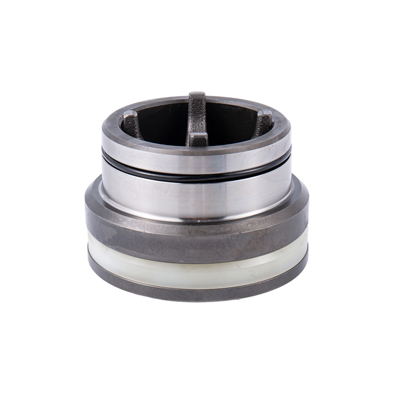
The reciprocating family splits into three primary geometries, each defined by the sealing element and the relationship between the drive component and the pumped fluid. Piston pumps seal at the moving element; plunger pumps seal at a stationary packing; diaphragm pumps isolate the fluid with a flexible barrier. That fundamental difference dictates pressure capacity, chemical compatibility, and service life.
| Type | Seal Location | Max Pressure (typical) | Media Compatibility | Typical Applications |
|---|---|---|---|---|
| Piston pump | Seal moves with the piston inside the cylinder bore | Up to 3,000 psi (low-pressure designs); some high-pressure units reach 7,500 psi | Clean, non-abrasive fluids; oils, hydraulic fluids | Hydraulic systems, chemical transfer, low-pressure metering |
| Plunger pump | Stationary packing at the cylinder head; plunger slides through the packing | 15,000 psi and above; standard in frac and well service pumps | Handles abrasive and corrosive fluids with proper plunger coating and packing material | High-pressure water jetting, hydraulic fracturing, acidizing, chemical injection |
| Diaphragm pump | No dynamic seal in contact with fluid; diaphragm acts as static barrier | Up to 1,200 psi (air-operated); higher for hydraulically actuated units | Highly corrosive chemicals, slurries with large solids, shear-sensitive fluids | Chemical dosing, mining dewatering, food processing, slurry transfer |
In high-pressure oilfield operations, the plunger pump dominates. The stationary packing is far easier to replace than a moving piston seal, and the plunger can be coated with tungsten carbide or ceramic to resist erosion from proppant-laden fluids. The diaphragm pump, while limited in pressure, excels where zero fluid leakage and absolute chemical isolation are non-negotiable.
Key Design Parameters for High-Pressure (15,000 psi) Reciprocating Pumps
When a reciprocating pump must generate 15,000 psi cycle after cycle, the fluid end body becomes a pressure vessel subjected to extreme cyclic fatigue. The two stress concentrators that dictate service life are the bore intersections — where the horizontal plunger bore meets the vertical suction and discharge bores — and the threaded areas that receive high-tension tie rods. A generic carbon steel casting will crack at these cross-bores in a few hundred thousand cycles. High-performance fluid ends instead rely on forged stainless steel and mechanical treatments that build residual compressive stress exactly where cracks would initiate.
Three engineering choices separate a fluid end that lasts years from one that fails in months:
- Material selection. Forged 17-4PH stainless steel with a yield strength greater than 120 ksi is now the baseline for severe service. The material’s corrosion resistance also guards against chloride stress corrosion cracking when pumping acids or produced water. For standard applications, a stainless steel fluid end built from this alloy often doubles the inspection interval compared to cast alternatives.
- Autofrettage. This cold-working process applies an internal pressure of 80% to 110% of the material’s yield strength, permanently yielding the bore surface in compression. After release, a zone of residual compressive stress blocks crack propagation at the critical bore intersections. The result is a 2x to 3x improvement in fatigue life at 10 million cycles.
- Forged vs. cast structures. Forging aligns the grain flow around the bore intersections and eliminates the micro-porosity that acts as a crack starter in castings. Under identical test conditions, a forged fluid end can demonstrate 30% to 50% higher fatigue strength than a casting with the same nominal alloy composition.
At 15,000 psi operating pressure, the pump’s plunger diameter, stroke, and speed are selected to balance flow rate with allowable rod load and packing life. Plunger speeds above 350 RPM shorten packing seal life dramatically, so the displacement formula becomes a tool for trading speed against diameter to stay within safe fatigue limits.
Common Failure Modes in Reciprocating Pump Fluid Ends
Every catastrophic fluid end failure begins with a small, identifiable mechanism that, if caught early, can be corrected without pulling the pump from location. Understanding the root cause behind a cracked deck, washed-out seat, or persistent packing leak is the difference between a scheduled repair and an unplanned shutdown.
| Failure Mode | Root Cause | Prevention |
|---|---|---|
| Stress corrosion cracking at bore intersections | Cyclic tensile stress combined with corrosive media (H₂S, chlorides); worst in cast carbon steel fluid ends | Use forged stainless steel; apply autofrettage; monitor pH and H₂S levels in fracturing fluid |
| Valve seat erosion and washout | High-velocity fluid jetting across partially open valves; abrasive solids (sand) accelerate material removal | Specify carbide valve inserts; replace valve insert seals at predetermined run hours; maintain proper suction pressure to avoid cavitation |
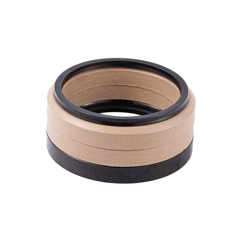
| Packing leakage and plunger scoring | Worn or improperly lubricated packing seals; misalignment of plunger; overheating from insufficient flush | Inspect packing daily for drip rate; maintain plunger alignment within 0.003 in; use correct packing material for fluid temperature and chemistry |
Each failure mode leaves a signature. A crack at the bore intersection often starts as a pinhole leak that progresses to a full-thickness break. A washed valve seat shows a polished, scalloped surface that indicates flow jetting. Packing failure first appears as a sudden increase in the required packing nut torque and a visible spray pattern. The key is linking those field observations back to a mechanical root cause rather than simply swapping parts.
How to Select the Right Reciprocating Pump for Your Application
The pump specification process is not a search for the highest pressure rating. It is a systematic elimination of options that cannot survive the fluid, cannot hit the required flow, or cannot be maintained with the available spare parts inventory. Frame the decision around three interconnected questions.
| Selection Parameter | Decision Guidance | Typical Solution Path |
|---|---|---|
| Maximum operating pressure and required flow rate | Determine the highest sustained pressure plus a 10% safety margin. Calculate theoretical displacement using the formula, then apply a volumetric efficiency of 0.90–0.95 for new seals. If the pressure exceeds 10,000 psi, a plunger pump with a forged fluid end becomes mandatory. | Map the pressure-flow point to a pump frame size. For frac applications, a 5,000 hp frame with a 4.5 in plunger delivers approximately 0.7–1.2 gallons per stroke at 250 rpm. |
| Fluid characteristics — abrasives, corrosives, gas content | For proppant-laden slurries, select a plunger pump with tungsten-carbide-coated plungers and hard-faced valves. For highly corrosive acids, switch to a diaphragm pump or a stainless steel fluid end with full alloy compatibility. Check free-gas fraction; above 5% by volume, reduce speed and increase suction pressure to protect valve seating. | Use 17-4PH stainless steel fluid ends with NACE MR0175 compliance for sour service. Specify ceramic plungers where sand concentration exceeds 2 lb/gal. |
| Fleet standardization and interchangeability | Operators running mixed fleets of SPM, Gardner Denver, and Halliburton pumps must verify fluid end dimensional interchangeability before ordering replacements. A design that bolts directly onto an existing power end saves days of modification. | Consult a detailed interchangeability guide to match replacement fluid ends to your legacy power end models, reducing procurement complexity and inventory SKU count. |
These three parameters often interact. A corrosive fluid at high pressure will demand a premium alloy, but that alloy must also be available in a forging that fits the power end. Skipping the interchangeability check is a common procurement error that leads to a perfectly functional fluid end that simply cannot be installed.
Maintenance Best Practices to Extend Fluid End Life
Fluid end maintenance is not about reaching a theoretical fatigue limit. It is about catching the small, visible indicators of wear before they become structural failures. A practical field program combines daily visual checks with run-hour-based component swaps.
- Packing inspection. Check packing nut torque and leakage rate daily. A properly adjusted set of packing seals should weep 6–12 drops per minute. A sudden increase requires either re-torquing or replacement before plunger scoring occurs.
- Valve seat condition. Record suction and discharge pressure differentials. A widening gap at a given flow rate indicates valve leakage. Plan to replace valve assemblies every 500–1,000 pumping hours in harsh proppant service, or when differential exceeds 5% above baseline.
- Bore intersection inspection. During scheduled shutdowns, use borescope inspection or magnetic particle testing to examine the critical bore cross-sections. A crack initiation of 1 mm is acceptable for continued short-term operation, but any detected crack should trigger ordering a replacement fluid end.
- Plunger alignment. Verify plunger concentricity relative to the stuffing box bore with a dial indicator. Misalignment beyond 0.003 in accelerates packing wear and induces bending stress at the clamp connection.
- Lubrication and flushing. Maintain plunger cooling and flushing fluid flow within the manufacturer’s specified range. Under-flushing causes overheating and packing burn-up; over-flushing wastes energy and can mask small leaks.
The decision to replace versus refurbish a fluid end depends on cumulative stress cycles and economics. A fluid end that has accumulated 80% of its calculated design life based on the cycle count should be retired at the next maintenance window, even if no visible cracks are found. The downtime cost of a catastrophic crack far exceeds the price of a new forging.
Conclusion: Why Understanding Reciprocating Pump Fundamentals Matters
Reciprocating positive displacement pumps are not just pumps; they are precision displacement machines whose reliability governs the economics of high-pressure operations. The fundamentals — fixed volume per stroke, independence from system backpressure, and predictable wear patterns — turn an abstract selection exercise into a manageable engineering discipline.
When you understand the stress concentration at a bore intersection, you specify a forged, autofrettaged fluid end instead of a standard casting. When you know that volumetric efficiency in a packing-leaking pump drops below 0.85, you schedule seal replacement based on run hours, not guesswork. That level of informed decision-making directly reduces non-productive time and procurement waste. For any team responsible for pump specification or maintenance, these principles are not optional — they are the difference between operating on plan and operating on emergency.
