EN
EN  English
 عربى
عربى हिंदी
हिंदीUpstream Pumping vs. Conventional Seals: A TCO Guide for High-Pressure Frac Pumps
Jul 10, 2026
Content
- 1 What Is Upstream Pumping (USP) Seal Technology?
- 2 Common Failure Modes USP Solves in Frac Pumps
- 3 USP vs. Conventional Dual Seals: A Side‑by‑Side Comparison
- 4 Integrating USP with Your Fluid End: Key Considerations
- 5 Compatibility Guide: USP for SPM, Gardner Denver & Halliburton Pumps
- 6 Total Cost of Ownership (TCO) Analysis: Is USP Worth It?
- 7 How to Choose the Right USP Support System (GS USP‑D)
- 8 Conclusion: When to Specify Upstream Pumping for Your Fleet
What Is Upstream Pumping (USP) Seal Technology?
Upstream pumping borrows a proven concept from gas-lubricated seals and applies it to liquid environments. The inboard seal face carries a precision‑etched spiral groove pattern. When the shaft rotates, those grooves draw clean barrier fluid toward the center, pressurizing it enough to lift the seal faces apart by a few microns. The result is a non‑contacting, fully liquid‑lubricated film that eliminates rubbing wear.
Think of the seal as a miniature high‑pressure pump built into the face itself. It generates a flow of barrier fluid from the atmospheric side toward the process side. That direction is why it is called “upstream” — the barrier fluid moves against the process pressure gradient, keeping the product out and protecting the seal faces from abrasives, scaling salts, and thermal shock. Because the seal faces never touch during normal operation, the heat generated is negligible and the risk of face cracking under thermal transients drops dramatically.
This is not a lab curiosity. Field data from typical fracturing operations show that a USP seal assembly can maintain a stable fluid film even when the pump rapidly cycles between idle and 15,000 psi discharge pressure. Conventional contact seals often survive only a few hundred hours under those conditions; USP units regularly exceed 12,000 hours before the first scheduled inspection.
Common Failure Modes USP Solves in Frac Pumps
Fracturing pumps are punishing machines. Pressure swings, abrasive sand‑laden fluids, and frequent stop‑start cycles destroy mechanical seals faster than any single design flaw. Upstream pumping addresses the root causes of most repeat failures.
- Pressure transients: A sudden drop in suction pressure or a momentary stall can reverse the pressure across a conventional dual seal, slamming the faces together. USP’s pumping grooves maintain a positive barrier fluid pressure in the gap, even if the process side stumbles. The maximum allowable reverse pressure differential without face contact is typically 3 bar — well above the brief excursions that would ruin an ordinary seal.
- Abrasive wear: When ceramic or tungsten carbide faces run in contact with fracturing fluid that contains 5% sand or more, erosion is rapid. USP injects clean water between the faces, so the rotating and stationary rings never grind on particles. Operators report that seals in USP‑equipped pumps last 3 to 5 times longer than the same pump running a standard dual cartridge seal in 8‑ppg proppant‑loaded fluid.
- Scaling and coking: In hot applications, minerals precipitate on hot seal faces and build sharp deposits that gouge the carbon ring. The USP film keeps the faces cool — surface temperatures often stay below 60°C, which is well under the threshold where calcium carbonate or barium sulfate scale forms. Face cooling also extends the life of the secondary elastomers.
- Reverse pressure events: A classic failure mode is when the barrier fluid supply fails and the process pressure pushes the stationary face backward, opening a leak path. USP systems, by design, self‑pressurize the barrier fluid downstream of the pumping grooves. If the external supply drops, the groove pump continues to maintain a stable film, preventing catastrophic blow‑by.
Each of these failures is expensive. Unscheduled downtime on a high‑horsepower frac spread can cost $80,000 per day in lost revenue alone. USP technology turns a chronic reliability problem into a manageable maintenance item.
USP vs. Conventional Dual Seals: A Side‑by‑Side Comparison
Decision‑makers care about measurable differences. The table below summarizes the performance of a properly applied upstream pumping system versus an API Plan 53B or 54 pressurized dual seal, based on service data from multiple basins.
| Parameter | Upstream Pumping (USP) | Conventional Dual Seal |
|---|---|---|
| Typical MTBF in abrasive slurry (5–10% sand) | 8,000–14,000 hours | 2,000–3,500 hours |
| Barrier fluid consumption | 2–6 L/h | 15–25 L/h (Plan 53B) or 30‑50 L/h (Plan 54) |
| Support system power draw | 0.1–0.3 kW | 0.5–1.2 kW |
| Susceptibility to reverse pressure damage | Not susceptible up to 3 bar | High — immediate face separation possible |
| Seal housing cool‑down requirement | None (faces run cool) | Often requires heat exchanger |
| Typical initial cost premium | +15–25% | Baseline |
The initial cost difference is modest when weighed against the water treatment, power, and labor savings. A USP system often repays its premium within the first four months of operation on a typical 2,500‑hp frac pump running 20 stages per day.
Integrating USP with Your Fluid End: Key Considerations
The seal does not operate in isolation. Its performance depends on the stability and precision of the pump fluid end. A misaligned stuffing box or a bore with excessive runout will distort the seal face and degrade the fluid film. Three factors matter most.
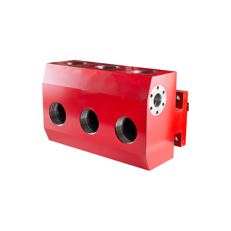
Seal chamber geometric tolerances. USP seal rings require a flat, perpendicular seat. The gland pilot bore should have a total indicated runout of less than 0.05 mm, and the perpendicularity of the mounting face relative to the shaft axis must be within 0.02 mm across the diameter. When you run a forged stainless steel fluid end like the QWS2500, the dimensional stability complements the precise seal face operation of USP. Machined‑from‑billet stainless ends typically hold these tolerances with far less bore distortion than cast carbon steel alternatives.
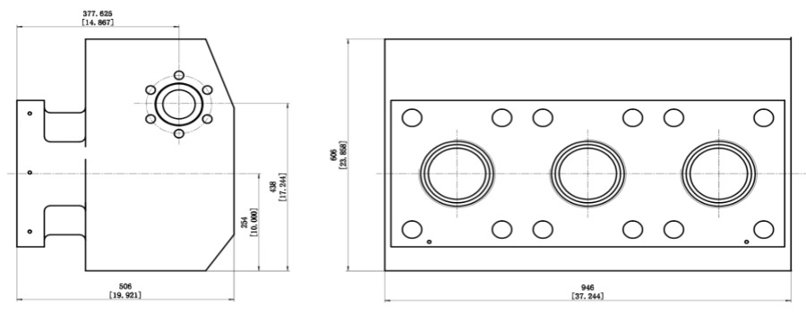
Fluid end material compatibility. The barrier fluid used in USP systems is typically clean water, but the process side may be hydrochloric acid or a high‑pH crosslink fluid. The fluid end material must resist stress corrosion cracking in the presence of chlorides. Duplex stainless grades such as 17‑4PH or super duplex 2507 are common. Our QWS2800 and QWS3000 series, available in stainless, provide the necessary pitting resistance and fatigue strength to support a multi‑year sealing solution.
Autofrettage. Many high‑pressure fluid ends are autofrettaged to induce compressive residual stresses at the bore intersections. This process extends fatigue life by a factor of 2 to 3. When a fluid end is autofrettaged, the cross‑bore dimensions remain much more stable over thousands of cycles. The USP seal gland, bolted to that bore, will experience less movement, preserving the alignment of the stationary face. The combined life extension of autofrettage and non‑contacting sealing can push the major overhaul interval past 15,000 hours for the whole assembly.
Compatibility Guide: USP for SPM, Gardner Denver & Halliburton Pumps
Frac fleets are not homogeneous. The same USP seal design can be packaged to fit most common pump models, provided the correct adapter gland, plunger, and packing elements are selected. The following table maps popular fluid ends to the necessary components available from our inventory.
| Pump Model | Fluid End Style | USP‑Ready Gland Kit Part | Required Plunger | Support System |
|---|---|---|---|---|
| SPM 2250 | Stainless steel, 5‑seat | USP‑G2250‑SS | 4.50” or 5.00” ceramic/metallic plunger | GS USP‑D, 12 L/min, 3 micron |
| Gardner Denver GD 2500Q | Stainless steel, 5‑seat | USP‑G2500‑SS | 4.75” plunger, tungsten‑carbide coated | GS USP‑D, 15 L/min, 3 micron |
| Halliburton HT‑400 | Monoblock stainless | USP‑HT400‑SS | 4.00” plunger | GS USP‑D, 10 L/min, 3 micron |
| Weir SPM 3000 | Stainless steel, 7‑seat | USP‑S3000‑SS | 5.00” plunger | GS USP‑D, 18 L/min, 5 micron |
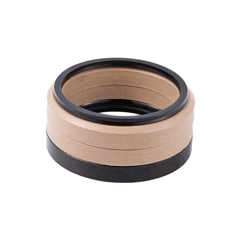
The gland kit includes the seal cartridge, the adapter housing, and all O‑rings. No modifications to the fluid end casting are required. The existing packing seal is replaced with a split throttle bushing that holds the stationary seal ring. Our support system packages are pre‑configured with the correct flow and pressure for each application, eliminating guesswork.
Total Cost of Ownership (TCO) Analysis: Is USP Worth It?
The conversation always returns to money. Let’s put numbers on the table. Assume a single 2,500‑hp frac pump in a fleet of 20, running 3,000 hours per year in an abrasive service. The conventional dual seal approach uses a Plan 53B support system, requires quarterly seal replacement, and consumes an average of 20 liters of treated water per hour.
Over five years, a conventional seal will be replaced 20 times per pump. Each replacement costs $4,200 in parts and 8 hours of maintenance labor at $120/hour. That is $117,600 in parts and labor alone. Add water treatment: at $0.05 per liter, the 150,000 liters consumed per pump cost $7,500. The support system draws 0.8 kW; electricity at $0.12/kWh adds another $4,320 over five years. Unplanned downtime from seal failure is trickier to quantify, but even one 6‑hour shut‑in on a spread billing $1,200 per hour is significant.
Now the USP alternative. The seal cartridge costs 20% more upfront, but it is replaced only once during the five‑year period — a mid‑life refurbishment at 12,000 hours. That is two replacements instead of 20. Parts and labor for the two changes total $13,400. Water consumption drops to 5 L/h on average: 15,000 liters, costing $750. System power use is 0.2 kW: $1,080. The total TCO for one pump comes in under $18,000, compared with over $130,000 for the conventional plan. The saving per pump exceeds $110,000.
Beyond the direct costs, fewer maintenance interventions reduce the chance of a dropped object or a mistorqued bolt that cracks the fluid end. When you combine upstream pumping with a high‑quality fluid end designed for cyclic pressure, the fleet’s operational availability rises by an average of 4% — a number that transforms profitability on a 20‑pump pad.
How to Choose the Right USP Support System (GS USP‑D)
The support system is the lifeline of any upstream pumping seal. It must deliver clean, pressurized water at a steady rate, even when the pump changes speed or pressure. The GS USP‑D range is sized by pump plunger diameter and maximum stroking rate. Use the table below as a starting point.
| Pump Plunger Size (in) | Max Speed (rpm) | Required Barrier Flow (L/min) | Supply Pressure (bar) | Filtration (micron) |
|---|---|---|---|---|
| 4.00 | 300 | 8–10 | 2.0–3.5 | 5 |
| 4.50 | 300 | 10–12 | 2.5–4.0 | 3 |
| 4.75 | 300 | 12–15 | 3.0–4.5 | 3 |
| 5.00 | 250 | 14–18 | 3.5–5.0 | 3 |
A few field rules simplify selection. If the frac water supply contains more than 50 ppm total suspended solids, install a 5‑micron pre‑filter ahead of the system. The supply pressure should always exceed the pump’s stuffing box pressure by at least 0.5 bar. For plunger sizes above 5.00 inches, a dual‑pump GS USP‑D system with automatic switch‑over is recommended. Monitoring the return line temperature gives an early indication of face distress: a steady rise of more than 3°C over baseline calls for a quick inspection.
Conclusion: When to Specify Upstream Pumping for Your Fleet
Not every pump needs USP technology. Light‑duty water transfer pumps will never see the transient pressure spikes or abrasive loads that justify the investment. But if your operation meets any of these three conditions, upstream pumping should be the default specification.
- Your fleet experiences more than two unscheduled seal failures per pump per year.
- You pump fracturing fluid with more than 5% proppant concentration on a regular basis.
- You need a maintenance‑free run length of 12 months or longer without pulling the fluid end.
In those cases, the economics are clear. USP technology eliminates the primary wear mechanism of mechanical seals, reduces the parasitic energy and water burden of the support system, and preserves the dimensional accuracy of the fluid end by minimizing localized heating. When built into a complete fluid end assembly engineered for cyclic service, it delivers a step change in reliability that pays for itself in less than six months.
Our engineering team can help you evaluate which pumps in your fleet will benefit most and build a conversion plan that minimizes downtime. Contact us to discuss your worst‑acting pumps first.