English
 عربى
عربى हिंदी
हिंदीHandling 15,000 PSI: Frac Fluid End Design Considerations
Mar 05, 2026
Content
- 1 Why 15,000 PSI Is a Different Engineering Problem
- 2 Material Selection: Carbon Steel vs. Stainless Steel at Ultra-High Pressures
- 3 Fluid End Block Geometry and Bore Intersection Design
- 4 Valve and Seat Design for 15,000 PSI Service
- 5 Plunger Selection and Packing System Considerations
- 6 High-Pressure Flow Iron and Manifold Design
- 7 Quality Assurance and Traceability Requirements
- 8 Maintenance Practices That Extend Life at Ultra-High Pressure
- 9 The Economics of Investing in the Right Equipment
Modern hydraulic fracturing has pushed well beyond what the industry considered extreme pressure just a decade ago. In tight shale formations like the Haynesville — where fracturing pressures routinely reach 13,500 PSI or higher — and in the deepest horizontal plays now demanding up to 15,000 PSI, the entire pump system is under a level of cyclic stress that most conventional designs were never engineered to sustain. As a manufacturer of high-pressure fluid end components, we work with operators and service companies facing these demands every day. What follows is a practical breakdown of the design considerations that actually matter at these pressures.
Why 15,000 PSI Is a Different Engineering Problem
There's a meaningful difference between designing for 10,000 PSI and designing for 15,000 PSI — and it's not simply a matter of adding more material. At extreme pressures, the dominant failure mode shifts from static overload to high-cycle fatigue. A fluid end on a typical frac job may see anywhere from 150 to 300 pressure cycles per minute. Over a 6- to 8-hour stage, that translates to millions of stress cycles on the fluid end block, plungers, valves, and seats.
The critical issue is stress concentration. Every bore intersection, threaded connection, and internal corner in the fluid end block is a potential crack initiation site. At 15,000 PSI, even small geometric imperfections that would be inconsequential at lower pressures can propagate into fatigue cracks within a single job. This is why design decisions about geometry, material selection, and surface treatment are inseparable from performance at this pressure class.
Material Selection: Carbon Steel vs. Stainless Steel at Ultra-High Pressures
For many years, high-strength carbon steel (typically 4330M or equivalent alloy grades) was the standard for fluid end blocks. Carbon steel offers excellent tensile strength — often in the range of 140,000–160,000 PSI yield strength — and it machines predictably. However, at 15,000 PSI with corrosive or high-chloride fracturing fluids, carbon steel's weakness becomes apparent: it is vulnerable to corrosion-fatigue, where chemical attack and mechanical stress combine to accelerate crack growth significantly faster than either mechanism alone.
Precipitation-hardened stainless steels — particularly 17-4 PH and 15-5 PH — have become the preferred material for demanding high-pressure applications. These alloys combine high yield strength (comparable to alloyed carbon steel) with substantially better corrosion resistance. In Permian Basin operations, stainless steel fluid ends have demonstrated service lives exceeding 3,000 pumping hours, compared to 800–1,200 hours that are more typical of carbon steel equivalents under similar conditions. The higher upfront cost is consistently offset by reduced replacement frequency and lower non-productive time.
| Material | Typical Yield Strength | Corrosion Resistance | Best Use Case |
|---|---|---|---|
| 4330M / 4140 Carbon Steel | 140,000–160,000 PSI | Low | Fresh water frac, lower pressure |
| 17-4 PH Stainless Steel | 155,000–170,000 PSI | High | High-pressure, corrosive fluid service |
| 15-5 PH Stainless Steel | 145,000–165,000 PSI | High | Ultra-high pressure, aggressive fluids |
| Duplex / Super Duplex | 90,000–116,000 PSI | Very High | Highly corrosive or sour service |
One critical but often overlooked factor is raw material cleanliness. Electro slag remelting (ESR) of the steel forging stock removes non-metallic inclusions and produces a more uniform metallographic structure. For fluid ends operating at 15,000 PSI, ESR-quality forgings are not a premium option — they are a baseline requirement for predictable fatigue life.
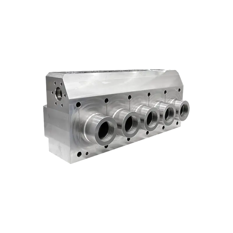
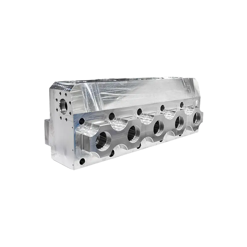
Fluid End Block Geometry and Bore Intersection Design
The fluid end block is where the highest stresses in the entire pump system are concentrated. In a triplex or quintuplex pump, the block contains multiple intersecting bores — the plunger bore, suction passage, and discharge passage all meet at a common chamber. This intersection is the most stress-critical region in the component, and its geometry largely determines fatigue life.
Transition Radius and Internal Surface Finish
Sharp internal corners act as stress risers. At 15,000 PSI, a corner radius of just 0.030 inches versus 0.090 inches can mean a 2–3× difference in local stress concentration factor. Quality fluid end manufacturers invest in precision CNC tooling specifically designed to machine generous, consistent internal radii at every bore intersection — this is not a detail that can be addressed during repair; it has to be built into the original forging and machining specification.
Similarly, internal surface finish matters. A bore surface with an Ra (average roughness) of 32 microinches versus 8 microinches can meaningfully increase fatigue crack initiation risk at high-cycle conditions. Polishing internal passages — particularly in the plunger bore and near bore intersections — is one of the highest-value finishing steps for 15,000 PSI components.
Shot Peening and Residual Compressive Stress
Shot peening introduces a layer of compressive residual stress at the component surface. Since fatigue cracks initiate and grow under tensile stress, a compressive surface layer directly counteracts crack initiation. For fluid end blocks operating at ultra-high pressures, controlled shot peening of critical bore surfaces can extend fatigue life by 20–40% under cyclic loading compared to an unpeened baseline, based on documented industry testing.
Valve and Seat Design for 15,000 PSI Service
Valves and seats are among the highest-wear components in any frac pump, and at 15,000 PSI, their design becomes a significant operational cost driver. The valve must open and close hundreds of times per minute against a fluid pressure differential that, at this pressure class, exerts enormous impact loading on the valve seat face with each closure.
Seat Geometry and Contact Angle
The contact angle between the valve and seat face determines contact stress at closure. A narrower contact band concentrates the seating force over a smaller area, improving seal integrity but also increasing wear rate. Most high-pressure valve designs for ≥10,000 PSI service use a 45° or 30° contact angle with a hardened insert at the seat face. The insert material — typically tungsten carbide or a hard-faced alloy — must withstand both the impact loading at closure and the erosive effect of abrasive proppant-laden fluid flowing past at high velocity.
Flow Area and Pressure Drop Across the Valve
At high pump rates (often 10–20 barrels per minute per plunger), pressure drop across the suction valve can reduce net positive suction head (NPSH) enough to cause cavitation on the suction side. Cavitation in a fluid end operating at 15,000 PSI is particularly destructive — the collapse of cavitation bubbles near metal surfaces produces localized peak pressures that can exceed 100,000 PSI at the micro-scale, causing rapid pitting damage. Valve designs with increased flow area relative to the plunger bore cross-section are therefore preferable for high-rate, high-pressure operations.
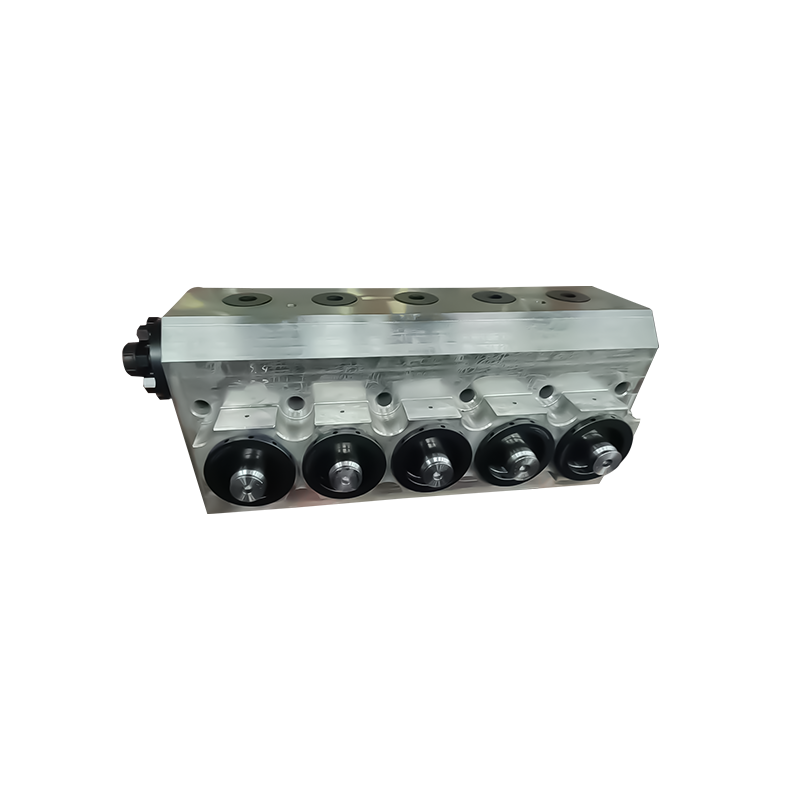
Plunger Selection and Packing System Considerations
The plunger and its associated packing system are among the most frequently serviced components in a high-pressure frac pump. At 15,000 PSI, the packing sees continuous dynamic loading — the seal must hold against a pressure differential nearly 1,000× atmospheric pressure while the plunger moves back and forth at up to 200 strokes per minute.
- Plunger diameter: Smaller-diameter plungers (e.g., 3.5" vs. 4.5") reduce the load on the power end at a given pressure, which can extend both plunger and packing life. However, smaller diameters reduce flow per stroke and may require higher RPM to maintain rate.
- Surface hardness and coating: Tungsten carbide-coated or solid ceramic plungers are standard for high-pressure service. Ceramic plungers offer excellent hardness (typically Rockwell 90+ HRA) and corrosion resistance, contributing to significantly lower wear rates compared to conventional chrome-plated steel.
- Packing material and geometry: HNBR and PTFE-based packing compounds are preferred for their chemical resistance and dimensional stability under high-pressure cycling. Multi-element packing stacks with a dedicated lantern ring for lubrication distribution outperform simpler single-element designs at 15,000 PSI.
- Lubrication system: Continuous forced lubrication to the packing is not optional at these pressures. Without adequate lubrication, packing life at 15,000 PSI can drop from hundreds of hours to a single job or less.
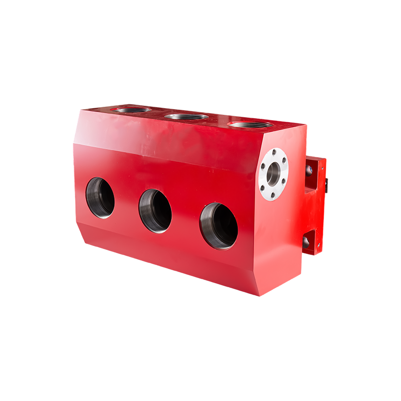
High-Pressure Flow Iron and Manifold Design
The fluid end is only one part of the high-pressure circuit. Downstream of the pump, the flow iron — hammer unions, treating iron, swivel joints, and wellhead connections — must be rated for the same working pressure class. A mismatch between the fluid end pressure rating and flow iron rating is a safety hazard and a common source of incidents.
For 15,000 PSI service, all flow iron components should carry a 15,000 PSI working pressure (WP) rating with a 2:1 safety factor, meaning a minimum test pressure of 30,000 PSI. API 6A governs wellhead and Christmas tree components in this pressure class, while API 7K covers pump and treating iron. Ensuring that all connections in the flow path are certified to consistent standards — including the hammer union thread forms and union seals — is essential for both integrity and personnel safety.
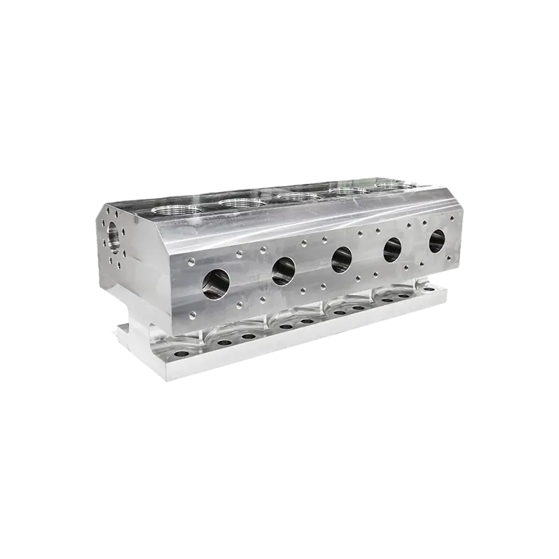
We manufacture and supply a broad range of high-pressure fluid end components and frac pump fluid end products designed for demanding well service operations — if you are sourcing components for your high-pressure circuit, we welcome the opportunity to discuss your specific requirements.
Quality Assurance and Traceability Requirements
At 15,000 PSI, a component failure is not an inconvenience — it is a safety event. This makes material traceability and non-destructive testing (NDT) non-negotiable rather than optional quality steps.
The following quality steps should be standard practice for any fluid end or flow iron component rated for ultra-high-pressure service:
- Material certification traceability from heat of steel through forging, machining, and final inspection — every component should carry a unique identifier traceable to its original material certificates.
- Magnetic particle inspection (MPI) or liquid penetrant testing of all critical surfaces after machining to detect surface-breaking defects.
- Ultrasonic testing (UT) of forging blanks prior to machining to detect subsurface inclusions or voids that would not be visible at the surface.
- Dimensional inspection using calibrated CMM equipment to verify bore geometry, thread form, and surface finish to specification.
- Hydrostatic pressure testing of assembled fluid ends to a minimum of 1.5× working pressure prior to delivery.
Operators sourcing aftermarket fluid ends should request the full quality documentation package — including raw material certs, inspection records, and test reports — as a standard procurement requirement. Any supplier unwilling to provide this documentation should be considered a risk at 15,000 PSI service conditions.
Maintenance Practices That Extend Life at Ultra-High Pressure
Even the best-designed fluid end will fail prematurely without the right maintenance regime. At 15,000 PSI, the margin for error is narrow. The following practices consistently differentiate operators who achieve long fluid end life from those who experience chronic failures:
- Controlled packing pre-load: Over-torquing packing nuts is one of the most common causes of premature plunger and packing wear. Use calibrated torque wrenches and follow the OEM specification — typically, packing should be snugged to the specified pre-load torque and then monitored for leakage rather than over-tightened pre-emptively.
- Pressure ramp-up protocol: Cold starting a pump directly to 15,000 PSI operating pressure stresses seals and packing before they have reached operating temperature and dimensional equilibrium. A staged ramp-up — bringing pressure to 50% for 2–3 minutes before going to full operating pressure — can measurably extend packing life.
- Routine valve and seat inspection: Establish a defined inspection interval based on pumping hours, not just job count. Worn seats that are left in service begin to channel — allowing fluid to erode a groove across the seating surface — and this quickly escalates from a minor wear issue into block damage that may require scrapping the fluid end body.
- Block crack inspection: After every major job or defined pumping hour interval, fluid end blocks should be inspected using MPI for early-stage fatigue cracks, especially around bore intersections. Catching cracks at 0.5–1.0 mm depth allows for block repair or planned replacement; finding them at 5+ mm typically means the block is scrap.
The Economics of Investing in the Right Equipment
The instinct to minimize upfront component cost is understandable, but at 15,000 PSI it is usually the most expensive decision an operator can make. Consider a scenario where a lower-cost carbon steel fluid end costs $18,000 and achieves 900 hours of service in a high-pressure, high-chloride application, versus a stainless steel equivalent at $28,000 that achieves 3,200 hours under the same conditions. The cost-per-pumping-hour is $20 for the carbon steel option versus $8.75 for the stainless steel option — a 56% reduction in component cost per productive hour, before accounting for the additional rig-up/down time, NPT, and logistics cost of the additional replacements.
This analysis changes further when you factor in the cost of an unplanned failure mid-job — lost pumping time, potential formation damage from job interruption, and the mobilization cost of replacement equipment. At 15,000 PSI, the cost structure strongly favors investing in higher-quality components, tighter quality assurance, and proactive maintenance intervals.
The design challenges of 15,000 PSI fracking operations are substantial, but they are well understood. Material selection, block geometry, valve design, packing system quality, and rigorous QA protocols together determine whether your fluid end investment performs reliably over thousands of hours or becomes a recurring cost burden. We design and supply our components with these specific demands in mind — if your operations are moving into this pressure class, we are glad to discuss what that means for your equipment sourcing decisions.