English
 عربى
عربى हिंदी
हिंदीUnderstanding Autofrettage: How It Boosts Fluid End Fatigue Life
Mar 10, 2026
Content
- 1 What Autofrettage Actually Does to Metal
- 2 Why Fluid Ends Are Particularly Vulnerable to Fatigue
- 3 The Two Primary Methods of Autofrettage
- 4 How Autofrettage Level Is Specified and Measured
- 5 Quantifying the Fatigue Life Improvement
- 6 The Role of Material Selection in Autofrettage Effectiveness
- 7 Practical Considerations When Specifying Autofrettaged Fluid Ends
- 8 Autofrettage Versus Other Fatigue Life Extension Approaches
- 9 Key Takeaways for Engineers and Operators
Autofrettage significantly extends the fatigue life of fluid ends — often by 2x to 5x or more compared to non-autofrettaged components — by inducing beneficial compressive residual stresses deep within the bore walls. This process counteracts the destructive tensile stresses generated during high-pressure cycling, which are the primary cause of fatigue crack initiation and propagation in fluid end components.
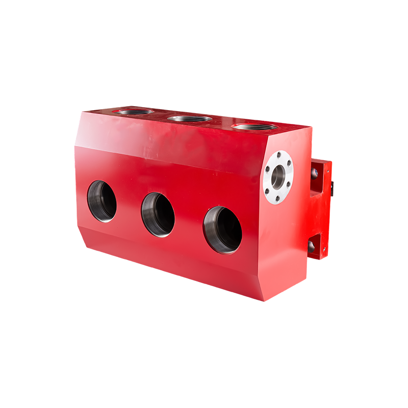
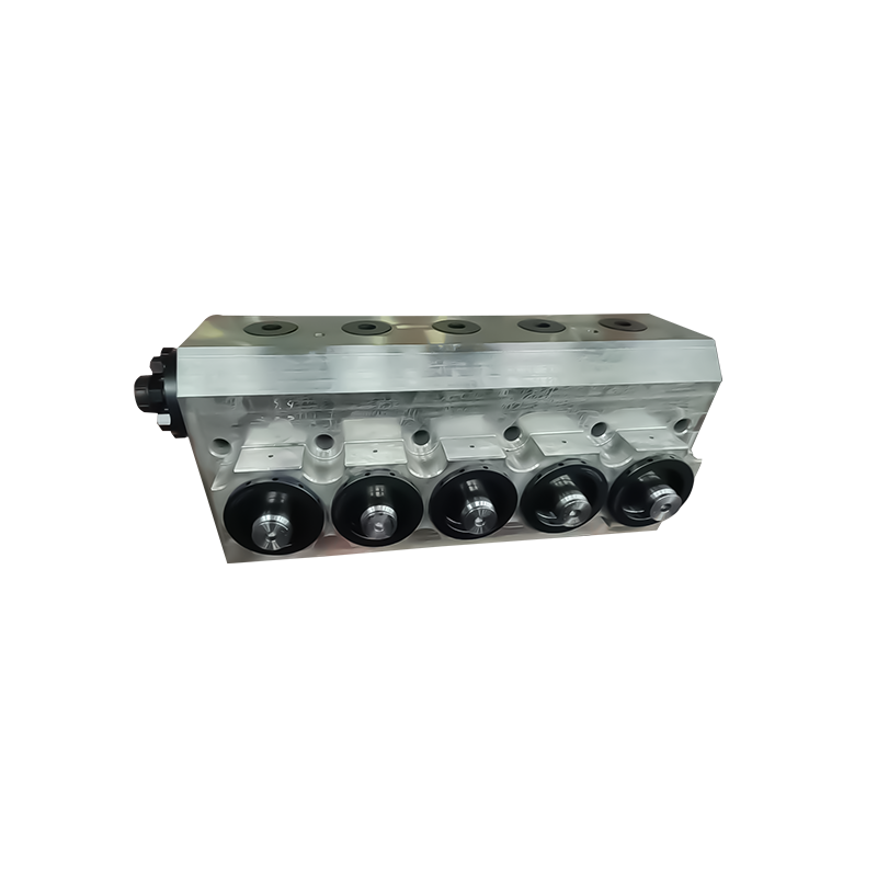
In high-pressure pumping applications such as hydraulic fracturing, the fluid end is among the most fatigue-vulnerable components in the entire system. Understanding how autofrettage works — and why it matters — is essential for anyone specifying, maintaining, or engineering fluid end equipment.
What Autofrettage Actually Does to Metal
At its core, autofrettage is a controlled overpressurization process. A thick-walled bore — such as those found in fluid end blocks — is deliberately pressurized beyond its yield strength. The inner layers of material plastically deform (permanently stretch), while the outer layers remain elastic.
When pressure is released, the elastic outer layers attempt to spring back to their original dimensions. But because the inner layers have been permanently deformed, they cannot return. This creates a tug-of-war: the outer material compresses the inner bore wall, leaving behind a zone of compressive residual stress at the most fatigue-critical location — the bore surface.
This compressive pre-stress must be overcome before any tensile fatigue stress can act on the material. Since fatigue cracks initiate and grow under tensile stress, the compressive layer effectively raises the threshold that cyclic pressures must exceed before damage begins.
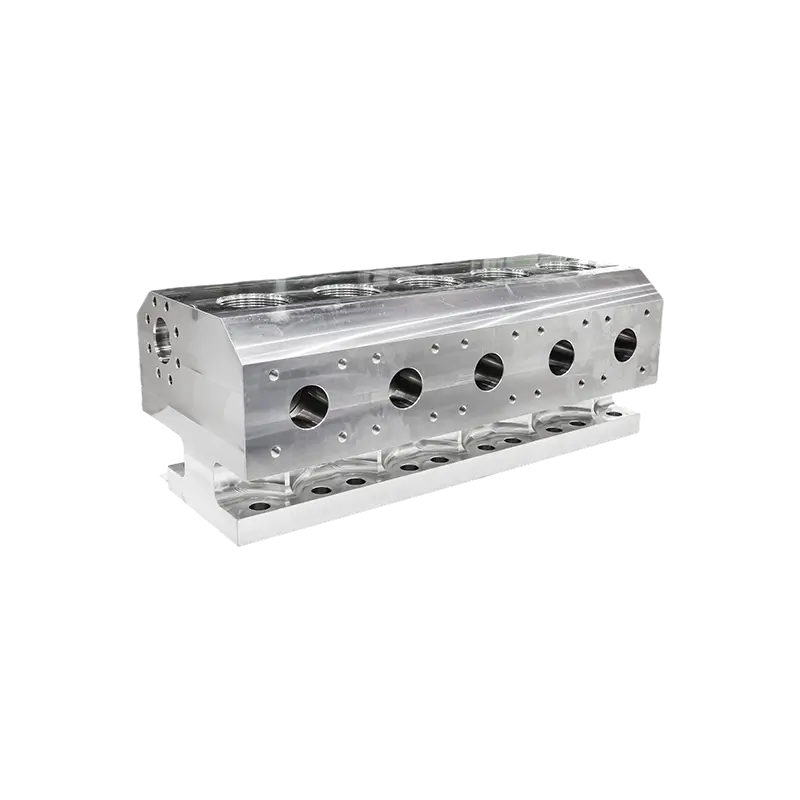
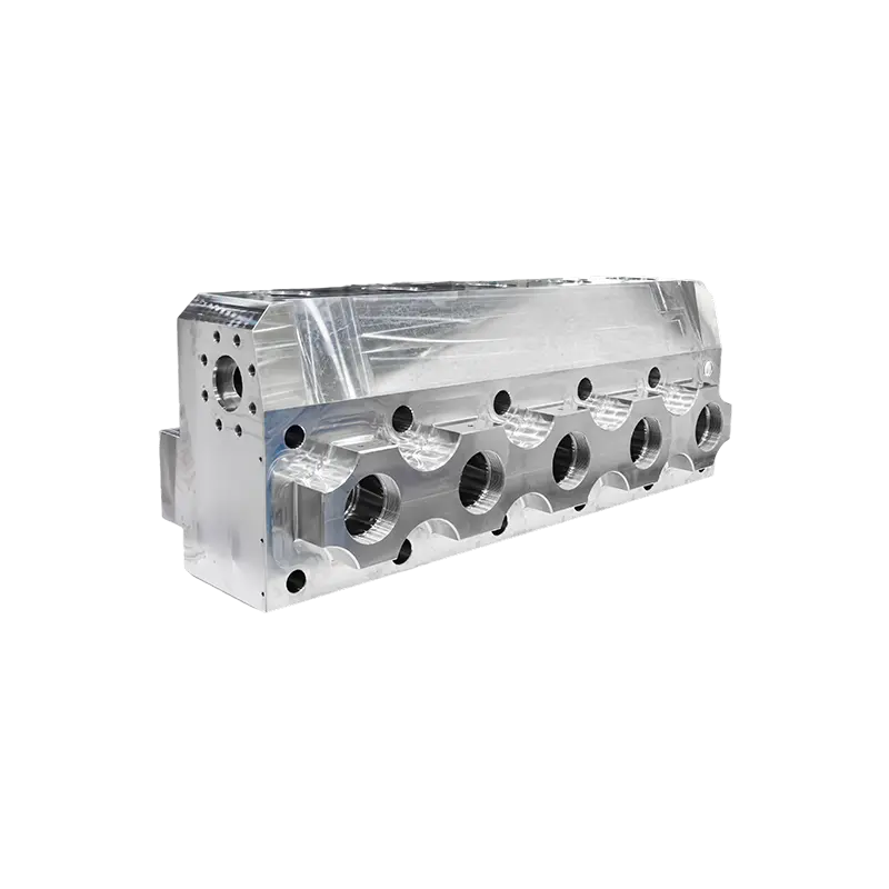
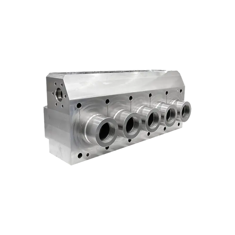
Why Fluid Ends Are Particularly Vulnerable to Fatigue
Fluid ends in fracturing pumps operate under some of the most punishing cyclic loading conditions in industrial equipment. Consider the typical environment:
- Operating pressures ranging from 5,000 to over 15,000 psi
- Cyclic pressure fluctuations occurring hundreds of times per minute
- Stress concentration points at bore intersections (cross-bores), valve seats, and threaded connections
- Exposure to abrasive, chemically active fracturing fluids
The geometry of a fluid end — particularly where bores intersect at right angles — creates stress concentrations that can be 3 to 4 times higher than the nominal hoop stress. These are the locations where fatigue cracks most commonly originate, and they are precisely where autofrettage delivers the greatest benefit.
The Two Primary Methods of Autofrettage
There are two established techniques for applying autofrettage to fluid end components. Each has distinct advantages depending on geometry, production volume, and required depth of the residual stress zone.
Hydraulic Autofrettage
This method uses ultra-high-pressure fluid — typically water or oil — injected directly into the sealed bore. Pressures of 60,000 to 100,000 psi or higher are applied to plastically expand the bore wall. Hydraulic autofrettage naturally conforms to the bore geometry, making it well-suited for complex fluid end configurations with multiple intersecting bores. The depth of the plastic zone can be precisely controlled by adjusting the applied pressure.
Mechanical (Swage) Autofrettage
A mandrel or ball slightly larger than the bore diameter is forced through the bore under high axial load. The interference fit between the mandrel and the bore wall creates the plastic deformation. Swage autofrettage typically produces higher surface compressive stresses than hydraulic methods and also improves bore surface finish. However, it is more difficult to apply uniformly in bores with varying diameters or complex intersections.
| Attribute | Hydraulic Autofrettage | Swage Autofrettage |
|---|---|---|
| Mechanism | High-pressure fluid | Oversized mandrel/ball |
| Suitability for Complex Geometry | High | Moderate |
| Surface Compressive Stress Level | Moderate | High |
| Surface Finish Improvement | Minimal | Significant |
| Depth of Residual Stress Zone Control | Precise (pressure-controlled) | Fixed by interference |
| Equipment Cost | Higher | Lower |
How Autofrettage Level Is Specified and Measured
Autofrettage is typically expressed as a percentage — the fraction of the wall thickness that has undergone plastic deformation. A 100% autofrettage means the entire wall has yielded; 50% autofrettage means the plastic zone extends halfway through the wall.
For fluid end components, autofrettage levels between 60% and 100% are commonly specified, depending on the wall thickness ratio (outer diameter to inner diameter) and the target fatigue life improvement. Higher autofrettage percentages generally yield greater fatigue life improvement, but there are diminishing returns and a risk of over-autofrettage causing yielding-induced damage if not carefully controlled.
Verification typically involves destructive sectioning with residual stress measurement using techniques such as:
- X-ray diffraction (XRD) — non-destructive surface stress measurement
- Neutron diffraction — measures residual stress through the full wall thickness
- Sachs boring method — destructive technique based on strain release during material removal
Quantifying the Fatigue Life Improvement
Published research and field data consistently demonstrate substantial fatigue life gains from autofrettage. Some representative findings:
- Studies on high-pressure cylindrical vessels show autofrettage can increase fatigue life by factors of 2 to 10, depending on the material, geometry, and applied autofrettage level.
- In fluid end cross-bore geometries — the most critical failure zone — autofrettage has been shown to reduce the maximum tensile stress range by 30% to 60% during operating pressure cycles.
- Field experience in fracturing operations frequently reports fluid end service life improvements of 3x to 5x when moving from non-autofrettaged to fully autofrettaged components of similar material grade.
The exact improvement depends heavily on the baseline (non-autofrettaged) design, the material's yield strength, and the operating pressure-to-yield ratio. Materials with higher yield-to-tensile strength ratios tend to benefit more from autofrettage because they can sustain larger compressive residual stresses without relaxation.
The Role of Material Selection in Autofrettage Effectiveness
Autofrettage is not a substitute for appropriate material selection — the two work together. Higher strength steels allow higher operating pressures and can sustain greater compressive residual stresses, but they are also more susceptible to hydrogen embrittlement and stress corrosion cracking in aggressive environments.
Common fluid end materials include:
- 4130/4140 chrome-moly steel — widely used, good balance of strength and toughness, responds well to autofrettage
- 17-4 PH stainless steel — improved corrosion resistance, used in more aggressive fluid environments
- Duplex and super-duplex stainless steels — highest corrosion resistance, increasing use in high-chloride applications
The Bauschinger effect — a reduction in compressive yield strength after prior tensile yielding — slightly reduces the theoretical maximum achievable residual stress after autofrettage. This effect is more pronounced in some steels than others and must be accounted for in fatigue life predictions. Modern finite element analysis (FEA) models incorporate the Bauschinger effect to generate accurate residual stress profiles for life calculations.
Practical Considerations When Specifying Autofrettaged Fluid Ends
When evaluating or specifying autofrettaged fluid end components, the following factors deserve close attention:
- Autofrettage level documentation: Request traceability records showing the autofrettage method used, the pressure or mandrel interference applied, and the resulting verified residual stress depth. Unverified claims of autofrettage provide limited assurance.
- Post-autofrettage machining: Any machining after autofrettage that removes bore surface material will partially or fully eliminate the compressive layer. Confirm that critical bore surfaces are not re-machined after the autofrettage operation.
- Heat treatment sequencing: Elevated temperatures — such as those encountered during stress relief or improper welding repair — can relax residual stresses. Autofrettage should be one of the last processing steps before final inspection.
- Pressure rating alignment: An autofrettaged fluid end specified for a lower pressure class than its operating conditions will see the compressive layer overcome more rapidly, negating much of the fatigue benefit. Always match the autofrettage level and pressure rating to actual operating conditions.
- Corrosion management: Surface corrosion in the bore can initiate fatigue cracks at stresses below the compressive residual stress threshold. Autofrettage does not eliminate the need for corrosion inhibition programs and appropriate material selection for the fluid chemistry involved.
Autofrettage Versus Other Fatigue Life Extension Approaches
Autofrettage is the most widely used and validated approach for extending fluid end fatigue life, but it is worth understanding how it compares to alternatives:
| Method | Mechanism | Typical Life Gain | Best Application |
|---|---|---|---|
| Autofrettage | Compressive residual stress at bore | 2x – 10x | All thick-walled bores |
| Shot peening | Compressive stress at surface | 1.5x – 3x | External surfaces, shallow bores |
| Increased wall thickness | Reduced stress magnitude | Moderate (diminishing returns) | New designs with weight budget |
| Higher strength material | Higher fatigue endurance limit | 1.5x – 4x | Combined with autofrettage |
| Bore geometry optimization | Reduced stress concentration factor | 1.5x – 3x | New designs, cross-bore relief grooves |
The most effective fluid end designs combine autofrettage with optimized cross-bore geometry (such as radiused intersections or stress-relief grooves) and appropriate high-strength material selection. These measures are complementary, not interchangeable.
Key Takeaways for Engineers and Operators
Autofrettage is one of the most cost-effective tools available for extending fluid end fatigue life in high-pressure cyclic service. Its benefits are well-established and quantifiable, but realizing those benefits requires attention to:
- Selecting the correct autofrettage method and level for the specific geometry and operating pressure
- Ensuring post-autofrettage processing does not undo the compressive stress layer
- Pairing autofrettage with compatible material selection and geometric design optimizations
- Maintaining fluid chemistry controls to prevent corrosion-assisted fatigue from bypassing the compressive residual stress protection
For any operation where fluid end replacement represents a significant share of maintenance cost and downtime, specifying properly autofrettaged components — and verifying that autofrettage — is one of the highest-return investments available.