English
 عربى
عربى हिंदी
हिंदीPump Failure Analysis: A Step-by-Step Guide for Fluid End Diagnostics
Jun 16, 2026
Content
- 1 Introduction: Why Pump Failure Analysis Matters in High-Pressure Fracking
- 2 The 4 Most Common Pump Failure Modes (and Their Signatures)
- 3 Deep Dive: Fluid End-Specific Failures (Cracking, Wear & Corrosion)
- 4 Step-by-Step Failure Analysis Process (With Decision Tree)
- 5 How to Diagnose Mechanical Seal Failure in Frac Pumps
- 6 The Role of Component Interchangeability in Pump Failures
- 7 Prevention Strategies: From Material Selection to Autofrettage
- 8 Conclusion: Build a Proactive Failure Analysis Program
Introduction: Why Pump Failure Analysis Matters in High-Pressure Fracking
At 15,000 psi, a single fluid-end crack can turn a $150,000 frac pump into a safety hazard in minutes. When a pump goes down mid-stage, the clock starts ticking on repair costs, standby equipment, and missed production targets. In many basins, an unplanned pump outage costs between $500 and $2,000 per hour — and the root cause is rarely obvious from the control room. A systematic pump failure analysis converts that chaotic downtime into a diagnostic pathway that finds the true failure mechanism, not just the symptom.
This article focuses on the high-pressure reciprocating plunger pumps that drive hydraulic fracturing. While general pump failure patterns — cavitation, contamination, overheating — apply across industries, frac pumps amplify these stresses through extreme pressures, abrasive slurries, and relentless duty cycles. The fluid end, where pressures transform rock, is the epicenter of most catastrophic failures. Mastering its failure signatures separates operators who schedule smart repairs from those who chase repeated breakdowns.
The 4 Most Common Pump Failure Modes (and Their Signatures)
Field data consistently shows that 90 to 95 percent of all pump failures trace back to four root mechanisms: aeration, cavitation, contamination, and excessive heat. In frac pumps, these mechanisms don't work alone — they cascade. Aeration starves a seal, which overheats, which then cracks a plunger, introducing abrasive sand into the power end. Understanding each signature is the first step in breaking that chain.
| Failure Mode | Physical Mechanism | Typical Symptom in Frac Pumps | Primary Prevention |
|---|---|---|---|
| Aeration | Air or gas entrainment causes bubble collapse at the suction eye and hydraulic unbalance | Slamming noise in fluid end, frothy fluid, fluctuating suction pressure | Maintain suction stabilizer charge, eliminate vortex in blending tub |
| Cavitation | Vapor bubbles form when suction pressure falls below fluid vapor pressure, then collapse implosively on metal surfaces | Distinctive "gravel" sound, pitting on plunger face and valve seats, reduced discharge pressure | Keep inlet vacuum under 5 inHg; use suction pulsation dampeners |
| Contamination | Solid particles (frac sand, pipe scale) abrade wear surfaces and wedge between close-tolerance components | Deep scoring on plunger ODs, accelerated packing wear, polished grooves in valve bodies | Use proper suction strainers and avoid low-velocity sand dropout in manifolds |
| Excessive Heat | Friction from dry running, bypassed pressure, or inadequate lube oil cooling degrades elastomers and reduces fluid film thickness | Blueing on plunger surface, softened O-rings, power end bearing spall, rapid seal carbonization | Maintain lubrification flow rate at design spec; never deadhead a frac pump |
In frac operations, contamination is particularly insidious. A plunger that loses only 0.002 inches of surface material from sand erosion changes the clearance in the stuffing box, immediately reducing volumetric efficiency and inviting packing blowby. The cascade then pushes heat into the power end lube system. Analysis begins with recognizing which pattern started the sequence.
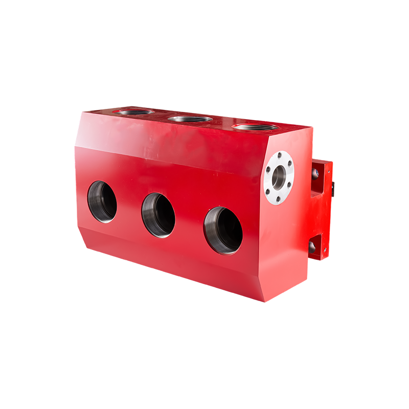
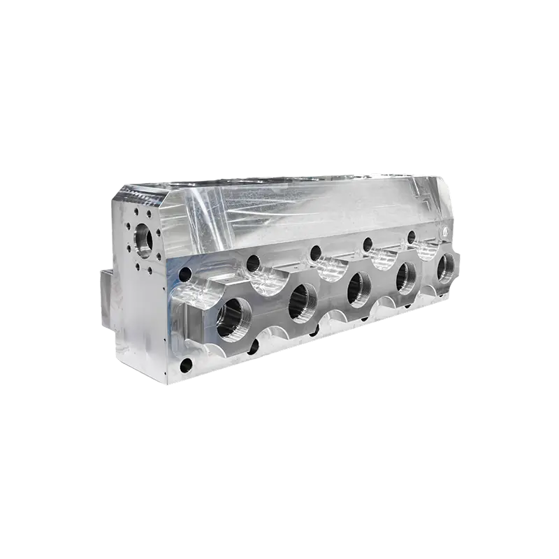
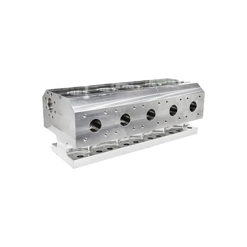
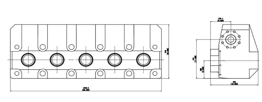
Deep Dive: Fluid End-Specific Failures (Cracking, Wear & Corrosion)
While bearings and seals fail in all rotating equipment, the frac pump fluid end has three failure modes that define its maintenance budget and lifecycle: cross-bore cracking, plunger surface wear, and valve seat erosion. These aren't generic pump failures — they arise from the immense cyclic pressures and the geometry of the fluid end block itself.
Cross-bore cracking is the costliest. The intersection of the plunger bore and the discharge bore creates a sharp stress concentration. Under repeated cycling from zero to 15,000 psi, tensile stresses at the bore intersection can exceed 80 ksi in carbon steel fluid ends, well above the material’s fatigue endurance limit. Once a crack initiates, it propagates with every stroke, eventually breaching the outer surface or connecting to the suction bore — destroying the forging. Stainless steel fluid ends processed with autofrettage, like the QWS2800 model, alter this equation by introducing compressive residual stresses at the bore wall, raising the effective fatigue strength and delaying crack initiation by thousands of hours.
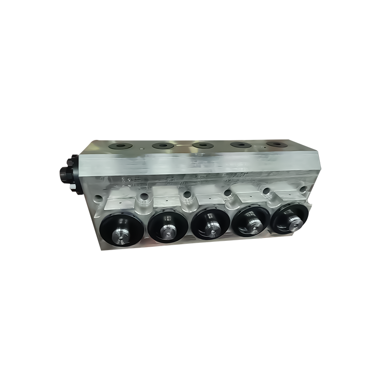
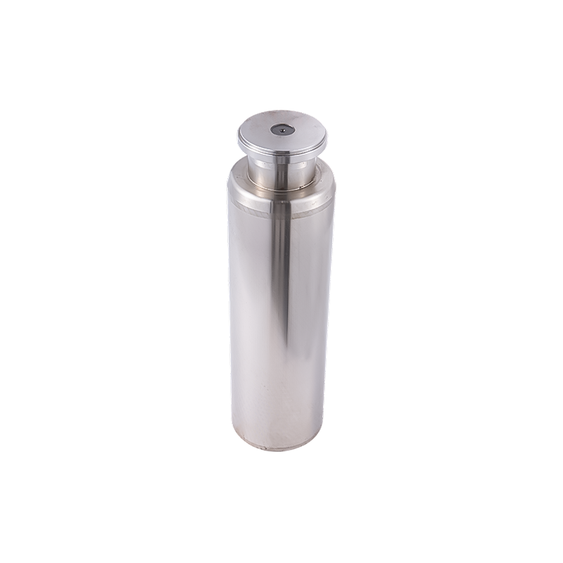
Plunger wear manifests in two distinct patterns: uniform diameter reduction from abrasive slurry, and localized scuffing from misalignment or insufficient lubrication. Wear rates above 0.001 inch per 100 hours signal a problem in the packing stack or a bent plunger. Once the plating or coating wears through, the base metal galls against the packing, destroying seal integrity. Pairing a worn plunger with a new packing set guarantees a short life.
Valve body and seat erosion follow the velocity path of the fluid. Erosion begins as polished depressions on the seat sealing face, then progresses to deep grooves that allow back-flow and hammering. The valve insert and seat interface is the first place to look when discharge pressure lags. On the fluid end assembly, using matched sets from the valve body and seat range ensures the sealing line remains intact longer than mixed-legacy parts.
Step-by-Step Failure Analysis Process (With Decision Tree)
A structured failure analysis stops you from tearing down the pump before you’ve ruled out simple external causes. The following decision tree starts with two quick field checks and branches into targeted inspections, saving hours of guesswork.
Decision Tree: "No Pressure" or "Abnormal Noise"?
- Is the pump producing rated discharge pressure? (Check gauge with transducer.)
- No — pressure low or zero: Go to Step 2.
- Yes — but abnormal noise or vibration: Go to Step 5.
- Measure suction-side vacuum at the pump inlet flange. Acceptable: below 5 inHg for frac pumps; ideally less than 3 inHg.
- Vacuum too high (above 5 inHg): Inspect suction manifold for collapsed hose, blocked suction strainer, or vortex in the blending tub.
- Vacuum normal: Proceed to Step 3.
- Check for bypassed flow. Close the discharge valve momentarily (if safe) and watch the pressure rise. Rapid pressure buildup suggests an internal leak path.
- Pressure rises quickly: Suspect failed valve seats, broken valve spring, or severely worn plunger/packing. Pull the fluid end covers and inspect valve inserts and seats visually.
- Pressure still low: Go to Step 4.
- Perform a displacement test on each plunger. Disable the power end and rotate the crankshaft to bottom-dead-center. Measure the plunger projection and compare to the last rebuild spec. If a plunger is retracted more than 0.125 inch beyond spec, the connecting rod or crosshead may have lost preload. Inspect the power end through the inspection covers — look for metal debris in the oil.
- Noise or vibration analysis: Place a hand on the fluid end block and the power end housing. A sharp, metallic knock synchronized with each stroke usually indicates a cracked fluid end at the bore intersection. A rumbling, grinding noise points to a failed main bearing or a broken crankshaft. Use a vibration meter: fluid end cracks typically generate broad-band high-frequency signals above 2 kHz.
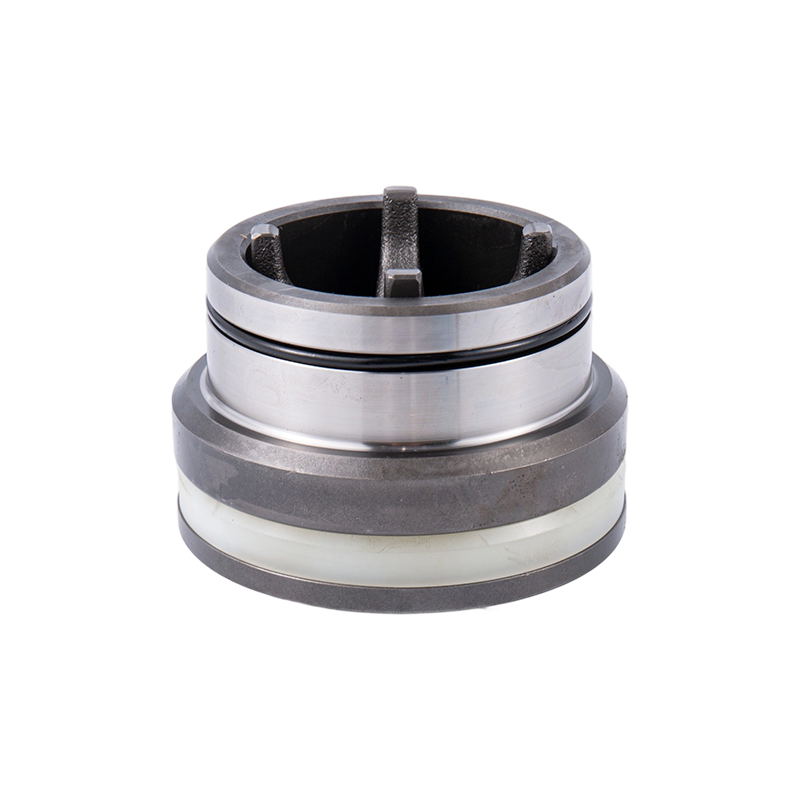
How to Diagnose Mechanical Seal Failure in Frac Pumps
Mechanical seals in the stuffing box are the frontline defense against fluid leakage along the plunger. A failed seal can flood the power end with abrasive slurry and degrade the lube oil, turning a $200 seal kit replacement into a $30,000 power end overhaul. Learning to read the seal face tells you exactly what went wrong.
| Seal Face Appearance | Root Cause | Corrective Action |
|---|---|---|
| Black heat-checking or radial cracks | Dry running from insufficient flush fluid or blocked leak-off port | Verify flush line flow rate; ensure packing lubrication bypass is not plugged |
| Fine, circumferential scoring with embedded particles | Abrasive contamination from frac sand bypassing the primary packing | Upgrade to dual-lip packing arrangement; check plunger surface finish |
| Corrosion pitting or softened elastomer backup rings | Chemical attack from acidic frac fluids or incompatible O-ring material | Switch to HNBR or FKM elastomers; confirm fluid chemistry compatibility |
| Uneven wear band or one-sided polishing | Plunger misalignment or bent plunger from improper clamp torque | Measure plunger runout at mid-stroke; torque plunger clamp bolts in sequence |
| Blistered face with melted polymer | Extreme heat from packing over-tightening or loss of coolant flow | Reduce packing gland torque to manufacturer spec; restore cooling water flow |
Always inspect the seal seat in the stuffing box bore as well. A worn or eccentric bore will misalign even a new seal, so run a dial indicator on the bore ID before installing a replacement.
The Role of Component Interchangeability in Pump Failures
One subtle but frequent failure driver is the use of non-genuine or low-quality interchange parts. A valve seat that is 2 points softer on the Rockwell C scale than the OEM spec may last 100 hours instead of 500. A plunger with 4 micro-inch less surface finish grade will accelerate packing wear by a factor of three. These failures often get misdiagnosed as generic "packing leakage" or "contamination" because nobody checks the individual part specifications.
Prior to any failure analysis, verify the provenance of the fluid end components installed during the last rebuild. Measure critical dimensions — valve seat outer diameter, plunger barrel roundness, seal groove depth — against the original engineering drawings. If the parts aren’t traceable, assume they contributed to the failure until proven otherwise. Interchangeable parts engineered to original or improved specs, such as those available from a dedicated fluid end parts program, eliminate the dimensional lottery. The minor upfront cost difference is trivial compared to a full fluid end replacement triggered by a single out-of-tolerance seat ring.
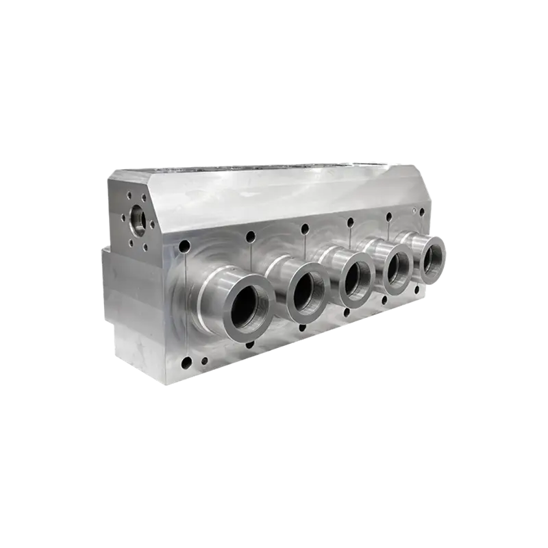
Prevention Strategies: From Material Selection to Autofrettage
Stopping failures before they start is a procurement and engineering decision as much as a maintenance one. Three strategies consistently deliver the highest return in frac pump reliability.
- Stainless steel fluid ends. Carbon steel fluid ends succumb to corrosion fatigue in sour or acidic brine environments. 2205 duplex stainless or 17-4PH forgings resist pitting and chloride stress corrosion, extending crack-free life by 40–60 percent in aggressive fluid conditions.
- Autofrettage. This pre-stressing technique hydraulically overloads the fluid end cross-bores during manufacturing, yielding the inner surface and leaving behind a beneficial compressive residual stress layer. The result: a 300 percent increase in fatigue cycle life compared to non-autofrettaged blocks, particularly at the bore intersections that normally initiate cracks.
- Forged monoblock construction. A one-piece forged fluid end, without weld seams or bolted joints, removes grain flow discontinuities that serve as crack nucleation sites. When selecting a fluid end, insist on multi-axis forging and complete ultrasonic inspection of the finished block.
Conclusion: Build a Proactive Failure Analysis Program
Every frac pump failure leaves a story written in the metal. A reactive maintenance team replaces the broken part and hopes for the best. A proactive program logs each failure, records the operating conditions, photographs the wear patterns, and builds a component-level history that predicts the next event. Start by downloading a standard failure analysis report template — include fields for suction vacuum, discharge pressure history, plunger wear measurements, and fluid chemistry. Review every failure with your parts supplier and engineering team. Over time, that database becomes your most powerful tool for turning unscheduled downtime into planned, low-cost interventions.